Ordering and fitting Stop Action Magnets (SAMs)
A few tips here might just save you a lot of grief. Firstly one golden rule: Once you have acquired your SAMs, do not be tempted to adjust them in any way, or allow someone else (however well meaning) to do so, unless they actually need it and the person carrying out adjustments actually knows what they're doing. I've seen more damage and faulty action caused by fiddling and tweaking than I would wish to!!!
This page is biased more towards Syndyne SAMs, although some aspects of Kimber Allen and original Compton units are catered for. Pneumatic action is not covered here, because it's thought unlikely that anyone would want to supply wind for a virtual instrument.
Let's sort out the Compton SAMs first. As the John Compton company no longer exists, manufacture has ceased, so acquisition of Compton SAMs is a matter of enquiry with one of the used parts suppliers. Therefore there are no part numbers or ordering codes. As with the other makes there are two main types - those with magnets and those without. The former (being the most prolific) are designed to be driven electrically by the organ's capture system as well as being capable of manual operation. The latter are for manual operation only. Ensure that you buy the correct variety for your needs.
Compton units are unique in that they usually have a Second Touch Cancel contact and spring fitted to each SAM. This allows the organist to use normal hand pressure to operate the tab and exert further pressure on any tab to turn all other SAMs off in their particular division. This is akin to having a Divisional Cancel button fitted to each tab. It's an ingenious system and works well when all SAMs are clean and correctly adjusted. However, in conjunction with the way that the signal contact is not usually isolated from the magnet coils, it can cause one particular problem for modern electronic capture systems. When these types of SAM are operated, they will cause a back-EMF or 'splash' to be relayed back from the magnet coil to the electronic drivers. In one case this proved to be disastrous and several expensive electronic units failed until the problem was rectified. If you are using Compton SAMs, tell the supplier of your control system and ensure that they send you units that can cope with the problem, or can supply a retrofit kit for existing units, otherwise buy a different control system (or design your own) that is guaranteed not to fail when used with Compton SAMs. Contrary to rumour, fitting diodes to the SAMs is not a cheap way to cure the problem.
Apart from 'bare' or 'with-magnets' varieties, Kimber Allen SAMs come in two styles for VTPO use. The standard 'SKA' Stop Key is usually mounted on a flat wooden board and can have a theatre style tab fitted, or can be used as a rocker action. The 'SKR' type is mounted vertically and can also have a tab or rocker tablet fitted. As with the Compton unit, it is normal practice to join one wire from each magnet coil together and join this junction to all other SAMs in the same fashion, as a 'Common' connection. In the past this connection has been routed to the Positive terminal of the supply and is known as "Positive Common". Decide whether you want to wire yours in the traditional fashion or in the opposite "Negative Common" manner and ENSURE that your driver electronics are configured for the correct polarity. Also, do not overheat the solder tag/s or you risk the tiny rivet that holds the main contact in place coming loose in the soft plastic mounting, which could give rise to unreliability.
Mounting the horizontal style K/A or Compton SAMs is fairly straightforward, simply fitting a wood screw through each mounting hole, onto a flat board below. The board can then be mounted level or tilted forwards. The tabs poke through a slot cut in the curved sweep or straight backboard. Ensure that the slot gives sufficient clearance so that the tabs and their mounting hardware do not hit the backboard during normal operation. You can also glue some thin felt below the tabs to embellish the layout and help to remove audible 'thump' from the SAMs. Vertical K/A SAMs are really only suitable for use on single row sweeps or straight backboards, as their front mounting plate is a bit too tall and would make vertical spacing between rows of tabs too great. Mounting them is similar to the method for mounting Syndyne SAMs.
Mounting tabs on Compton or K/A SAMs may give you problems. Genuine or replica Compton tabs on Compton SAMs will be fine as they're intended to go together. With some other tabs, especially those from the USA, you may need to file or grind flat a plastic 'pip' that some manufacturers provide, but is only really suitable for Syndyne SAMs. You may also need to either re-drill the mounting holes or bore a small hole in the underside of the tab and use a self tapping screw to secure it. If you do bore the underside, a fixed drill press with an adjustable depth gauge is essential.
With Syndyne SAMs it's extremely important to order the right ones for your installation and there are quite a few options. Below is a chart to help you.
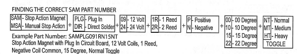
You need to pay particular attention to the Positive/Negative and the Degree (operating arm angle from horizontal) parameters. If you get any of the other parameters wrong, you can probably get round that without too much trouble, but make a mistake with polarity or angle and it will cause you a lot of grief and maybe great expense, so listen up (TAKE HEED).
Let's deal with the angle first as it's the easiest to understand. If your backboard or sweep bolsters are mounted exactly vertical then the tabs will be at an angle offset from horizontal. The default is 15 degrees, but as you can see from the chart, other angles are possible. 0 degrees is normally only used for rocker tablets and not for standard tabs. If you get this angle wrong, you might just be able to tilt a perfectly straight backboard to compensate, but it will likely never look right. With a curved bolster it is physically impossible to tilt it in all directions at the same time, so if your tab angle is wrong, you're stuffed. You might just be able to put an angled spacer behind each SAM, but it would be a heap of work and surely it's better to just order correctly angled SAMs in the first place?!

The importance of correct polarity is a little more obscure, but nevertheless considerable. It has to be said that the electromagnets will work when power is applied, regardless of polarity. The problem comes with the extraneous magnetic field that is generated by the coils. When correctly operated, the field from either magnet is polarised to add to the field within the permanent magnets which take the place of springs to keep the tab in a fixed position and to operate the reed contact/s on each SAM, NOT to oppose the field. If the coils are operated with the opposite electrical polarity to what they were designed for, the magnetic polarity also reverses and now opposes the permanent magnets. This tends to effectively make the holding field weaker and often causes unreliable operation under capture control, but that's not all. It's not the SAM that's actually being electrically operated that goes unreliable, but the ones to either side of it and to make matters worse, the distance between SAMs is also a significant factor. To make matters even worse, if multiple adjacent SAMs are being operated simultaneously, there will be a complex reaction between the coil fields and the permanent fields, which is almost impossible to predict. This has had engineers banging their heads, wondering what is wrong with their capture system/power supply, when all along they have the wrong SAM type. As with Degree, get Polarity right and you won't suffer! The procedure is to check what polarity your capture system uses or if there is a choice, pick the one that suits your system best and order Syndyne SAMs to match.
The other Syndyne ordering parameters are fairly self explanatory and are mainly a matter of choice. Voltage will be dependent on your power supply. I prefer to solder my wiring looms direct to the SAM PCB, but you may prefer to use sockets to plug onto the SAM pins and with at least one system (Opus 2) you have to connect with sockets and cannot solder direct.
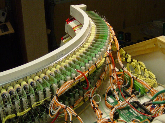
Syndyne SAMs use a mounting plate which has a fixing hole top and bottom and past practice has been to use a wood screw through each hole to secure them to a wooden bolster. When you are using multiple rows of stops, the SAMs can be used as the spacer to hold each rail one above the other and can actually be mounted with their plates almost touching each other horizontally, vertically or both. A far better method is to use a metal band (mini-channel) which is an extruded aluminium channel available from Mouser Electronics. Note that the picture shown on the Mouser site is incorrect, but other details are OK. The photo below (left) shows the channel as it really is. This will bend to shape around the back of the bolster and allows you to fit a nut or plate which has a threaded hole, inside the channel and either use short bolts or threaded studs and nuts to secure the SAMs.
A clasp is also shown below (right) to give you an idea of the shape of the plate you'll need to fit the channel. You can buy these clasps from Mouser, but they are rather expensive for our purposes and would cost you around $2 for every SAM (two per SAM). Not only that, the screw would either need to be modified as it's too short for a Syndyne SAM plate, or you'd have to discard it and fit a different one, which would make them even more expensive! My suggestion is to buy some brass stock around 13mm wide and no thicker than 2mm and make your own. Clamp several lengths of brass strip together, one on top of the other and use a drill press to bore a pilot hole for a 3mm (approx) thread, through the stack at the centre position for each plate (you can make a small pin-jig to line up each hole when drilled, ready for the next hole). Then fit an appropriate thread tap to a cordless drill and (using a low torque setting) tap a thread in each hole, using the reverse facility on the power tool to remove the tap from the hole. If your tap 'bottoms-out' your drill should prevent damage by slipping on its torque clutch. Finally, cut each plate to size using either a band-saw (with a metal cutting blade sprayed with WD40) or a guillotine press.

Mini-channel.
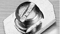
Clasp to secure mini-channel.
If you make your plates slightly smaller than the width of a SAM mounting plate (2 plates for each SAM) you'll find that you can align the tabs exactly where you want them, then tighten the fixing bolts. However, be warned!! If you let your screwdriver slip, you may well ruin a coil winding as the wires are very thin. Pozidriv (not Philips) screw heads, hex heads or best of all, Allen screws should solve this problem, or you could make or buy a thin shield to fit over the coils whilst fitting the SAMs.
Tip: ALWAYS mount Syndyne SAMs with a small gap between each one. This prevents magnetic fields from circulating through the steel plates, which can cause eratic switching problems. If you're tight for space, paint some varnish down the edge of each mounting plate, to prevent them from physically touching.
Depending on the tab style, tabs are normally be mounted in one of three ways. Using one top screw and nut, with the second hole in the arm taking the 'pip' on the back of the tab, provided to prevent twisting in use. Using two 'through' screws and nuts or using one top screw and a self tapping screw through the back of the arm into the underside of the tab.
Fabrication of curved stop-rails (bolster sweeps) is not an easy task and is best carried out by a competent carpenter. The method often employed is to make a jig of the curved profile and fit stout dowels to it (broom handle is good for this) then clamp thin (3 ply) plywood sheet to it in successive layers, with an even coating of PVA wood adhesive between each layer, until the desired thickness has been achieved.

Each successive layer should be rotated 90 degrees from the one below, so that the grains oppose each other for stability. Allow at least 24 hours for the glue to dry before removing the assembly from the jig. Use good quality close-grained birch plywood which will be easier to bend and especially for the outer surface, as modern high-gloss finishes will tend to expand open-grained veneer and will look rather unpleasant. Also, use grain filler before applying any finish.
One further word of warning: When making curved bolsters, using mini-channel, don't forget to allow about 12mm for the thickness of the mini-channel, otherwise you'll end up having to rout a groove in the wooden lamination, or else your tabs will sit too far back!
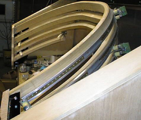
Look closely at the photo above to observe how the layers are built up. The photo below shows a cross-section of a multiple stop rail, giving details of how each row is stepped back from the row below.
